Download
On BitBucket here.
The jarfile works for everyone, and the .deb provides filetype association and dash search for Debian-derived OSes (like Ubuntu).
The jarfile can be executed as ./gcodeeditor.jar on *nix command lines, and takes a path to a gcode file as a single argument. With the .deb, you can use it from anywhere on the command line as gcodeeditor.
What does it do?
This program is meant make it easy to tweak the output of your slicer program, not to replace the slicer. The use-case which prompted its creation was needing to tweak the GCode of a solder stencil, since default slicers don’t do very well with thin objects needing some fine details. It handles the GCode well enough you don’t need to have memorized the spec, though some knowledge can help. It’s pretty much click-and-drag; pick a command to cut, cut it, add new commands in the gap, and then save. For a more detailed look at what it does and why, see below.
A brief introduction to GCode and the need for this program
RepRap-like 3D printers use a flavor of a language called ‘GCode’ to encode instructions for creating a form. GCode takes the form of a text file with one command on each line. The commands are low-level instructions for moving motors and other components; a line might look like M129 P1000, where M129 is the wait command, and P1000 is a 1000ms (1 second) duration. It is possible to write GCode by hand using a text editor, but it is very difficult because GCode encodes spatial data. Luckily, programs called ‘slicers’ exist to turn 3D models like STLs or OBJs to GCode. These programs are great, but their general-purpose algorithms tend to run into issues with some strange geometries. The GCode slicers output in these cases is typically almost what the users wants, but need some human intervention. Changing the code with a text editor is tedious at best and futile at worst, so I wrote a program to allow the easy graphical editing of these files.
Use case
I’m printing solder stencils to allow me to fabricate environmental sensors more easily and reliably. However, my current design iteration (more on that in a later post) uses a couple 0603 SMD components. 0603 components are absolutely tiny, which is why the solder stencil is necessary: I place the circuit board under the stencil (which has a raised lip to help align the board), then use a little plastic slide to apply solder paste to the stencil. Holes in the stencil deposit solder on the circuit board. Then, I remove the stencil, place components on the little solder pads, and heat the entire assembly to allow the solder to flow. Because the stencil is about 0.5mm thick, it deposits plenty of solder; since I use professionally printed boards, the solder flows accross the surface of the metal pads but does not leap to other pads easily because of a coating called soldermask, which repels it. If anyone has used crayons and watercolors to produce small patches of watercolor, it works on much the same principle. However, if there is solder already connecting the pads when the board is heated, it is virtually guaranteed to make bridges, shorting out the component.
This is a problem because many slicing algorithms treat two closely-spaced holes on a single-layer-thick print as one hole, perhaps expecting to split them on a nonexistent second layer. Now, because of the thickness of the stencil (and the resulting abundance of solder), I don’t mind covering some of the pad with stencil, but I do mind bridging two pads. Unfortunately, the merged hole causes a large bridge to appear, and there is no setting for such a specific use case in Slic3r. This is where the program (which I have unimaginatevly titled ‘GCode Editor’) comes in. Using the program, I am now able to correct Slic3r’s output to add a single extrusion command to separate the pads. Conveniently, the program reorders commands, alters their extrusion parameters to match, and inserts G92 (coordinate reset) commands as necessary to avoid altering the rest of the program.
Pictures
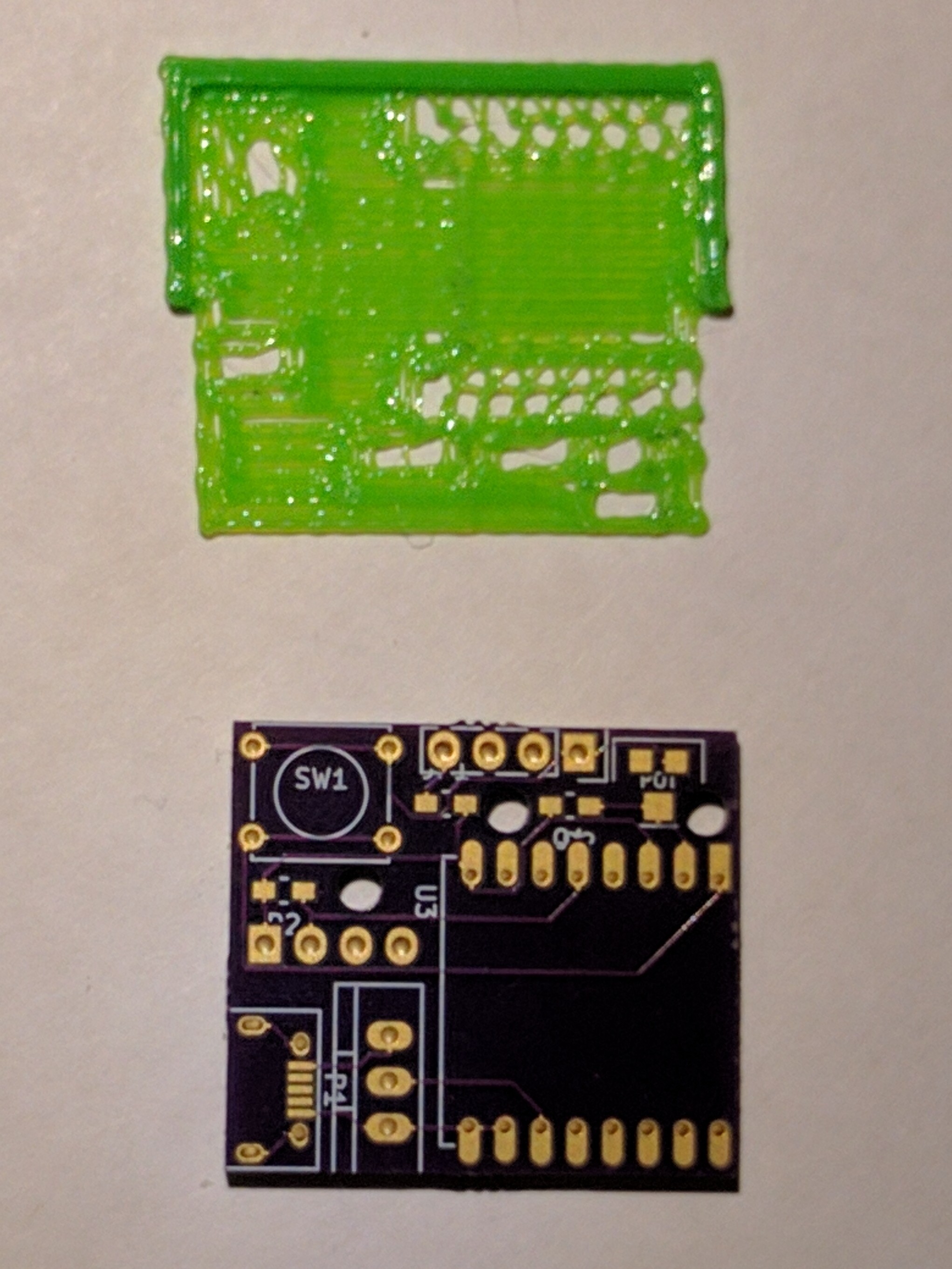
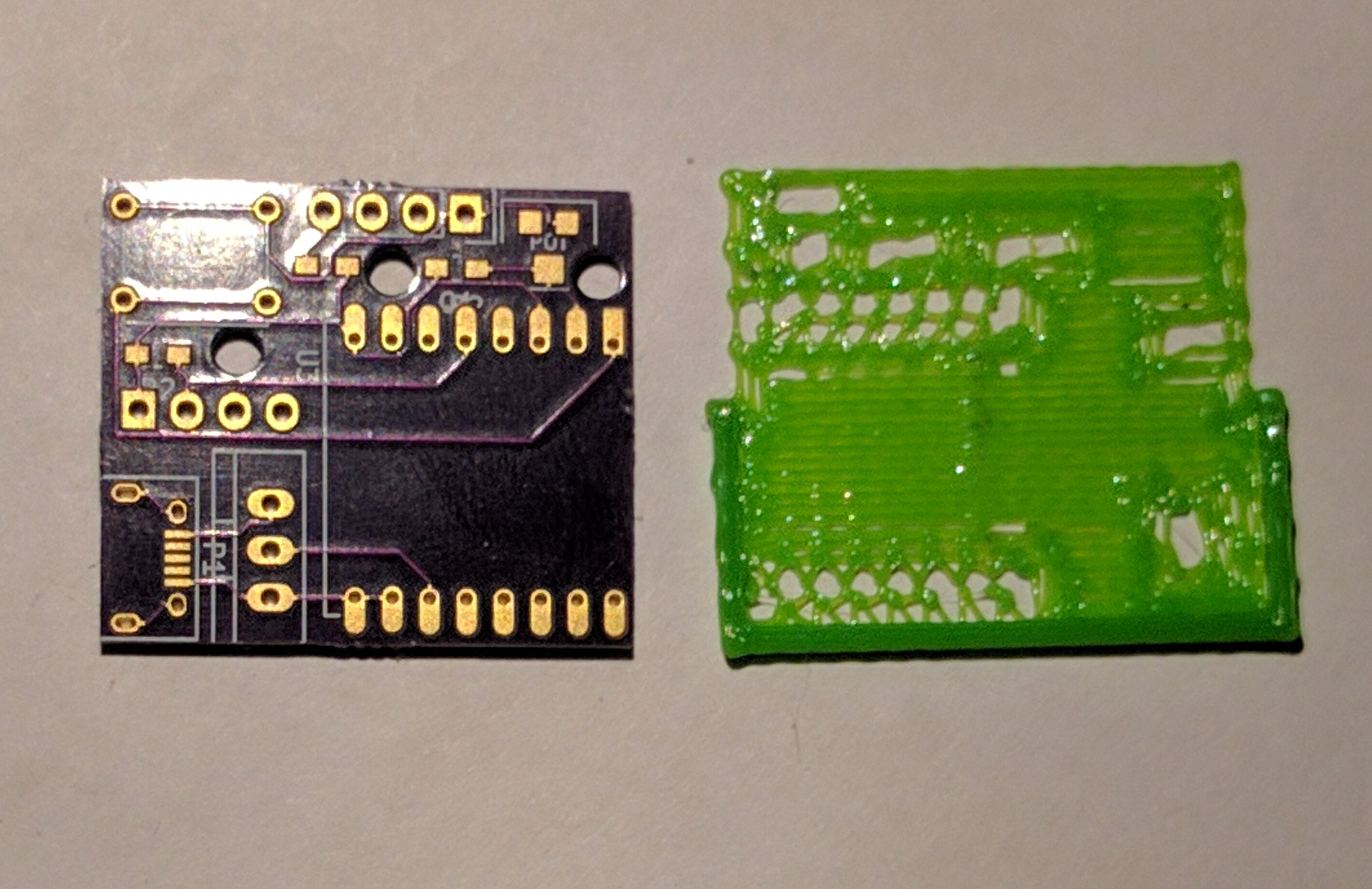
Above: an uncorrected soldermask and the circuit board it covers. Note some pairs of pads on the board correspond to a slot on the mask; this causes bridges.
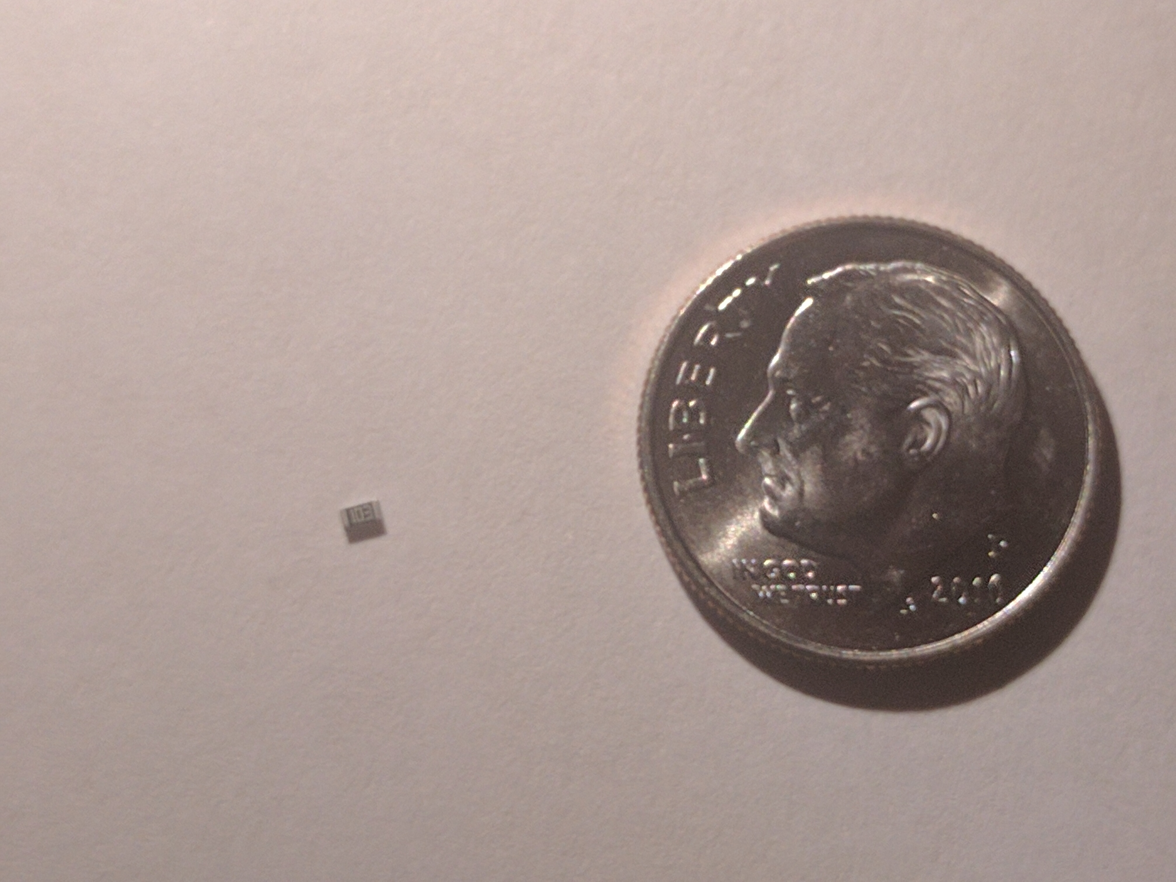
Above: the resistor format which makes the tiny pads and the tiny solder mask necessary.
Caveats
The program does not have any sanity checks, instead assuming the user knows what is and isn’t possible for their printer. At present, the program does not have dedicated support for multiextruder programs. That said, it is fairly stable and completely open source, so the best way to see if things work is to try them and if you need a feature which isn’t in there, I invite you to add it.